
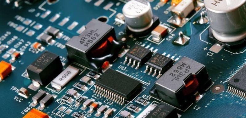
Surface mount assembly is widely used to manufacture modern electronic products that need compact circuit boards, consistent component placement, and an efficient production process. For US-based product developers, OEMs, and electronics businesses working with an assembly partner, understanding the advantages of surface mount technology (SMT) can help inform decisions about PCB design, prototyping, and production planning. This guide explains how surface mount assembly works, where it is most useful, how it compares with through-hole assembly, and what to prepare before requesting a manufacturing quote.
What Is Surface Mount Assembly?
Surface mount assembly is a PCB assembly method in which electronic components are mounted directly onto conductive pads on the surface of a printed circuit board. The components used in this process are called surface-mount devices (SMDs), while surface mount technology (SMT) refers to the manufacturing approach.
Unlike traditional through-hole assembly, which inserts component leads through drilled holes in the board, SMT generally allows components to be placed on one or both sides of a PCB without requiring a separate hole for each component lead.
This approach is well suited to many modern electronic products, including industrial controllers, connected devices, consumer electronics, LED products, communication equipment, and sensor-based systems.
The benefits depend on the board design, component selection, and manufacturing requirements. A well-planned SMT design can help teams make better use of board space and establish a repeatable assembly process.
Key Advantages of Surface Mount Assembly
The main advantages of surface mount assembly include compact layouts, automated component placement, flexible design options, and suitability for a wide range of production volumes.
1. More Compact PCB Designs
Surface-mount components are often smaller than comparable through-hole parts and do not require component lead holes. This gives designers more flexibility when arranging components and routing traces.
For products with limited internal space, such as connected sensors, control modules, and portable electronics, SMT can help reduce the board’s footprint. Components may also be placed on both sides of a PCB when the design and assembly process support it.
Smaller components do not automatically guarantee a smaller finished product. Enclosure dimensions, connector access, thermal management, and service requirements still need to be considered during design.
2. Efficient, Repeatable Assembly
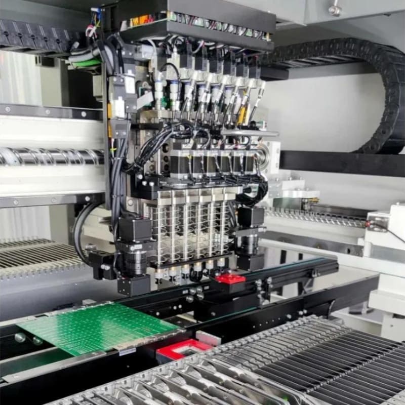
Automated pick-and-place equipment positions components on the PCB, while reflow soldering creates electrical and mechanical connections between components and board pads.
Because these steps can be controlled and repeated, SMT is suitable for manufacturing boards with many components and consistent placement requirements. The actual throughput depends on component mix, board complexity, equipment setup, inspection requirements, and production planning.
For product teams planning repeat orders, a repeatable process can make manufacturing easier to manage as designs move from prototypes to production.
3. Flexibility for Different Production Stages
Surface mount assembly can be used for prototype builds, pilot runs, and production orders. However, the most practical setup depends on the board’s complexity, component availability, programming and inspection needs, and order quantity.
A prototype may require additional engineering review and setup, while a repeat production order may benefit from established process settings and verified manufacturing documentation.
When requesting a quote, provide the expected quantity and whether additional builds are likely. This helps the assembly provider assess the appropriate manufacturing approach.
4. Support for High-Density Electronics
SMT allows designers to use small component packages and place components close together when the electrical and manufacturing requirements permit.
This can be valuable for boards with microcontrollers, communication interfaces, memory devices, and other integrated circuits. Fine-pitch components and dense layouts still require careful attention to PCB footprints, solder-mask design, component spacing, thermal pads, and inspection access.
The goal is not simply to fit more parts onto the board. It is to create a design that meets its electrical requirements and can be assembled and inspected consistently.
5. Potential Benefits for Electrical Performance
Shorter connections and compact layouts can help reduce parasitic inductance and capacitance in some circuit designs. This can matter in high-speed or high-frequency applications.
However, electrical performance depends on the complete circuit and PCB layout, including trace geometry, grounding, return paths, stack-up, component placement, and signal integrity requirements. SMT alone does not guarantee better electrical performance.
Surface Mount Technology vs. Through-Hole Assembly
Surface mount technology and through-hole technology serve different purposes. SMT is commonly used for compact, high-density electronic designs, while through-hole assembly remains useful for components that need particular mechanical support or are better suited to leaded mounting.
| Consideration | Surface Mount Assembly | Through-Hole Assembly |
|---|---|---|
| Component mounting | Components attach to PCB surface pads | Component leads pass through drilled holes |
| Board space | Often supports compact layouts | Holes and lead spacing affect layout |
| Automation | Well suited to automated placement | Automation depends on component and process |
| Typical applications | ICs, resistors, capacitors, LEDs, compact modules | Certain connectors, switches, transformers, and mechanically stressed components |
| Design considerations | Fine-pitch spacing, solder paste, thermal pads | Hole sizes, lead spacing, mechanical retention |
| Mixed assembly | Can be combined with through-hole parts | Often used alongside SMT on the same board |
Many electronic products use a combination of both methods. For example, a control board may use SMT for integrated circuits and passive components while using through-hole connectors where the design calls for additional mechanical support.
The right approach depends on the actual components, board construction, operating environment, and assembly requirements—not on choosing one method for every part.
What Is the Difference Between SMT and SMD?
SMT stands for surface mount technology, the method used to assemble components onto a PCB. SMD stands for surface-mount device, the component designed for that method.
In simple terms, SMT is the process, while SMD refers to the component.
Understanding the distinction is useful when discussing PCB design files, component packages, assembly requirements, and manufacturing quotations.
The Surface Mount Assembly Process: From Design Files to Finished PCBAs
A successful surface mount assembly project starts with complete documentation and a clear understanding of the product’s requirements. Reviewing the design before production can help identify missing information and manufacturing concerns before they cause delays.
A typical SMT assembly workflow includes the following stages.
1. PCB File Review and Design for Manufacturability
The assembly team reviews the available design files, bill of materials (BOM), component placement data, drawings, and assembly instructions.
This review may identify issues such as mismatched footprints, missing polarity information, unclear component orientation, or incomplete revision details. The exact files required depend on the project and manufacturing arrangement.
2. Solder Paste Printing
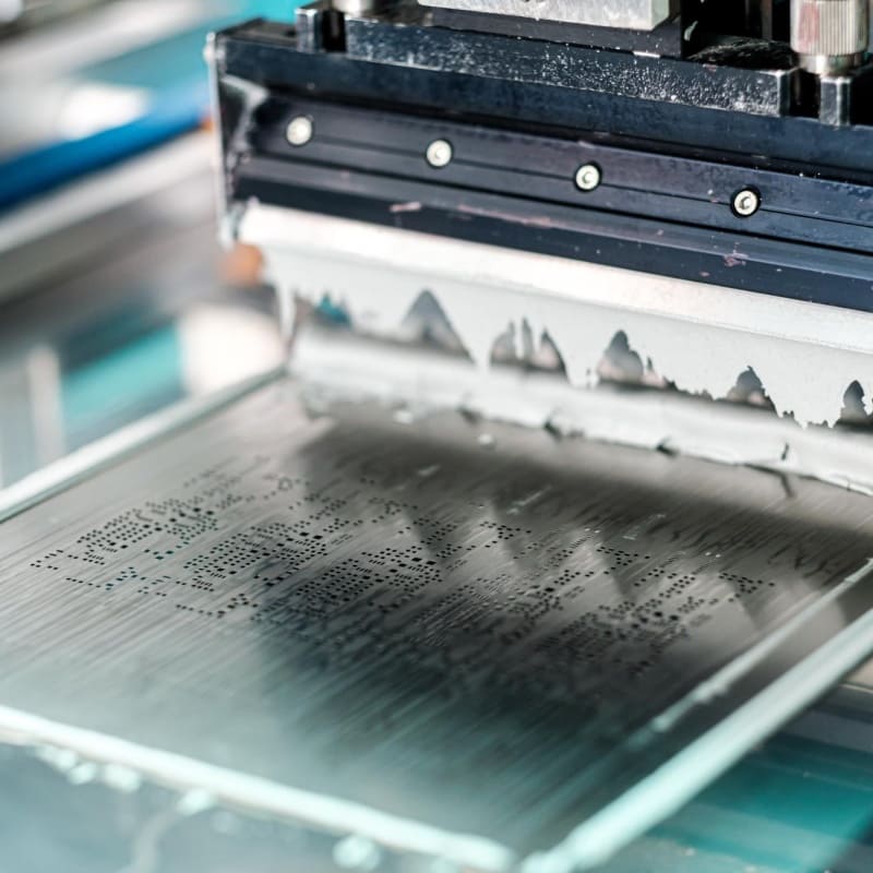
Solder paste is deposited onto designated PCB pads, typically through a stencil. The stencil design, paste properties, PCB condition, and printing setup affect how consistently the paste is applied.
Insufficient or excessive solder paste can contribute to assembly defects, so this stage requires suitable process control.
3. Automated Component Placement
Pick-and-place equipment positions surface-mount components according to the approved placement data.
Component size, package type, orientation, feeder setup, and board design all influence the placement process. Fine-pitch devices and small passive components may require additional attention during design review and production setup.
4. Reflow Soldering
The populated PCB passes through a reflow oven, where a controlled thermal profile melts the solder paste and forms solder joints.
The appropriate profile depends on the solder alloy, component thermal limits, PCB materials, and assembly requirements. A single temperature profile should not be assumed suitable for every design.
5. Inspection and Testing
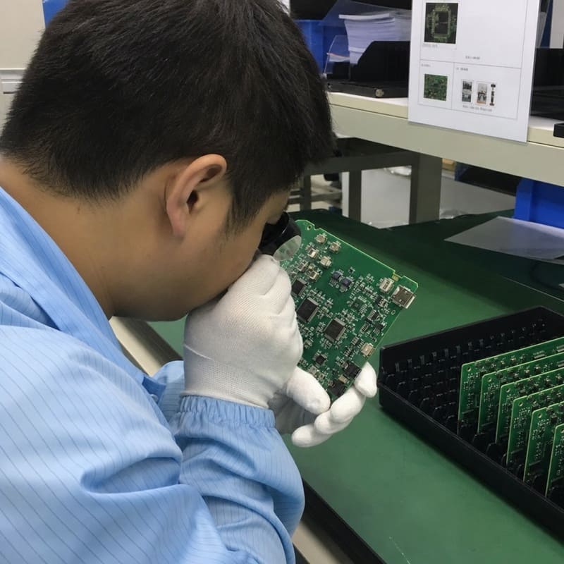
After soldering, the assembled board may undergo visual inspection, automated optical inspection (AOI), X-ray inspection, electrical testing, or functional testing as required.
Different inspection methods detect different types of problems. For example, AOI can help identify visible placement and soldering issues, while X-ray inspection can be useful for examining certain hidden solder joints.
The appropriate inspection and testing plan should be based on the board’s components, intended function, and quality requirements.
6. Final Handling and Delivery
Depending on the project, additional steps may include programming, cleaning, conformal coating, labeling, packaging, or integration into a finished enclosure.
These services should be specified during quotation so that the manufacturing plan reflects the complete product requirement rather than assembly alone.
SMT Assembly Design Guidelines: A Practical DFM Checklist
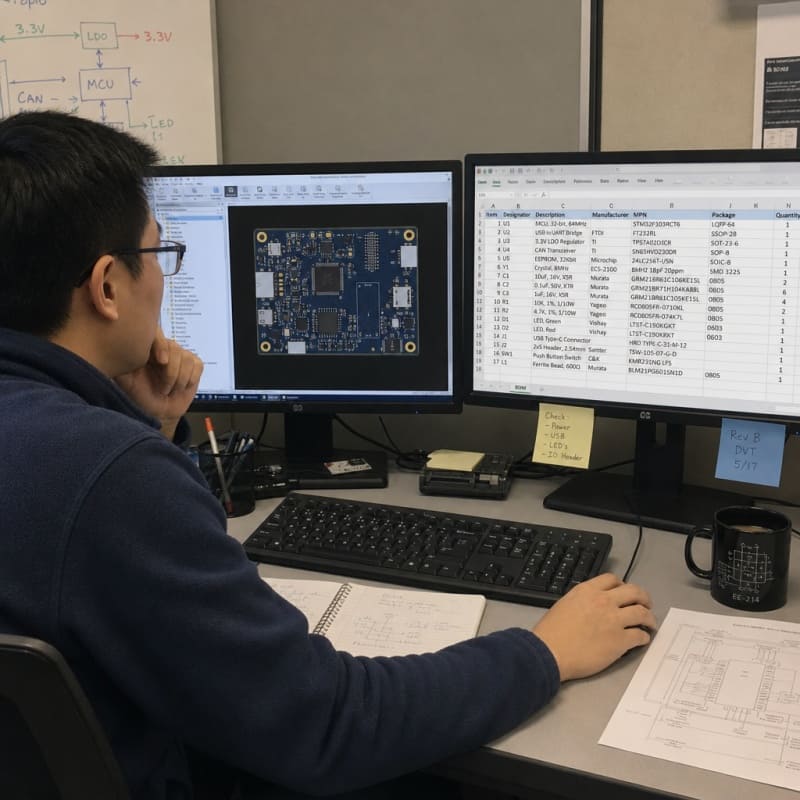
Design for manufacturability (DFM) is the process of reviewing a design to identify potential manufacturing issues before production. For SMT projects, a practical DFM review helps align the PCB layout, component data, and assembly instructions.
Before requesting a quote, check the following items:
Component footprints: Confirm that footprints match the exact parts listed in the BOM.
Polarity and orientation: Clearly identify polarized capacitors, diodes, LEDs, IC orientation, and connector direction.
Reference designators: Keep component labels readable and avoid placing important markings beneath components.
Fine-pitch components: Review pad geometry, solder-mask clearance, and spacing for the selected package.
Thermal pads: Confirm the intended paste pattern and thermal design for components with exposed pads.
Component spacing: Allow sufficient clearance for placement, inspection, and possible rework.
Panelization: Include appropriate tooling features and fiducials where required by the manufacturing process.
BOM completeness: Include manufacturer part numbers and identify approved alternatives when appropriate.
Test access: Identify test points and programming interfaces needed for verification.
Revision control: Make sure the Gerber files, BOM, placement file, and assembly drawings refer to the same design revision.
This checklist is a starting point, not a substitute for a project-specific engineering review. Requirements can vary by component package, PCB construction, assembly equipment, and testing plan.
If the design is still being finalized, ask the assembly provider to review the available files and identify any missing information before committing to production.
Applications of Surface Mount Technology
Surface mount technology is used across a broad range of electronic products because it supports compact circuit layouts and automated assembly.
Industrial Electronics
Industrial controllers, monitoring equipment, power management boards, and automation systems often use SMT to integrate processors, sensors, communication interfaces, and control components.
For these products, the design may also need to address vibration, operating temperature, electrical noise, and long-term component availability.
Consumer Electronics and Connected Devices
Smart home products, portable devices, connected sensors, and other consumer electronics frequently require compact boards with multiple integrated functions.
SMT can help designers accommodate these functions within limited space, provided that the layout also accounts for heat, antennas, connectors, and enclosure constraints.
Automotive Electronics
Automotive electronic products may include control modules, sensor electronics, infotainment systems, and other vehicle-related circuits. The required environmental, reliability, and validation standards depend on the specific application.
Manufacturers should confirm the relevant requirements for the product rather than assume that all automotive electronics follow the same process or qualification criteria.
Medical Electronics
Medical electronic equipment can use SMT in monitoring devices, control boards, and other electronic assemblies. Applicable quality, safety, and regulatory requirements vary according to the intended use and product classification.
LED Lighting and Power Electronics
LED products and power-control boards may use SMT for compact component placement and integration. Thermal management, current requirements, component spacing, and heat dissipation remain important design considerations.
Choosing an SMT Assembly Partner
The right assembly partner should understand the design requirements, communicate potential manufacturing issues, and explain which services are included in the proposed build.
When evaluating an SMT assembly provider, consider the following questions:
Can the provider review Gerber files, BOMs, placement data, and assembly drawings before production?
Does its process support the component packages and board complexity required for your project?
Can it explain the inspection and testing options available for the application?
Can it coordinate component sourcing if you need support with procurement?
Can it support the production stage you are planning, from prototype builds to repeat orders?
Does the quotation clearly identify included services, assumptions, exclusions, and any additional setup or testing costs?
A useful quotation should be based on your actual project information. Price comparisons are more meaningful when all providers are quoting the same revision, component list, quantity, and testing requirements.
Fuxin PCBA provides PCB assembly services for prototype, low-volume high-mix, and production projects. Its listed capabilities include SMT and mixed-technology assembly, component sourcing, and a range of inspection and testing services. Review the specific requirements and availability for your project with the team.
Learn more about Fuxin PCBA’s PCB assembly services.
Future Trends Shaping Surface Mount Technology
Surface mount technology continues to evolve alongside changes in electronic product design. Smaller component packages, denser layouts, and more complex electronic functions are increasing the importance of precise design data and manufacturing feedback.
Several trends are worth watching:
More compact component packages: Smaller packages can support space-constrained designs but may demand more careful footprint design, placement, inspection, and rework planning.
Increasing board density: As more functions are integrated into a board, layout, thermal management, and inspection access become more important.
More data-driven process control: Production data and inspection results can help manufacturing teams identify process variation and investigate recurring issues.
Earlier design-for-manufacturing reviews: Bringing assembly expertise into the design process can help identify potential manufacturing concerns before the first build.
Greater emphasis on component availability: Alternative-part planning and accurate BOM data can help teams manage sourcing challenges without making unapproved substitutions.
For buyers, the practical lesson is straightforward: complete design documentation and early communication make it easier to assess manufacturing risks and plan a build.