
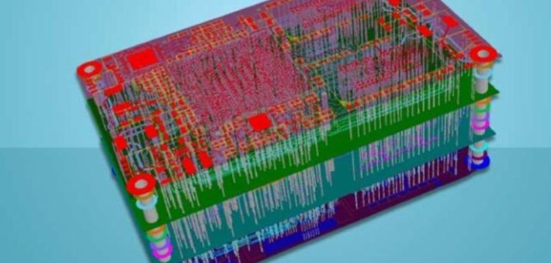
Introduction to PCB Stackup Design
A well-designed PCB layer stackup is critical for signal integrity, power delivery, and electromagnetic compatibility (EMC) in modern electronics. Whether you’re designing a 4-layer PCB for consumer electronics or a complex 10-layer board for high-speed applications, understanding proper stackup techniques ensures optimal performance and manufacturability.
This comprehensive guide covers:
✔ Essential PCB stackup design principles
✔ Comparison of 4-layer, 6-layer, and 10-layer configurations
✔ Best practices for high-speed and EMI-sensitive designs
✔ Manufacturing considerations for optimal yield
Why PCB Stackup Matters for Your Design
Key Benefits of Proper Stackup Design
-
Improved Signal Integrity – Controlled impedance routing reduces reflections and crosstalk
-
Enhanced Power Delivery – Tight power-ground coupling minimizes noise
-
Better EMI/EMC Performance – Proper shielding prevents radiation
-
Manufacturing Reliability – Symmetrical designs prevent warping
Critical Stackup Design Factors
-
Layer arrangement (signal, power, ground distribution)
-
Dielectric material selection
-
Impedance control requirements
-
High-speed signal considerations
Best PCB Stackup Configurations Compared
1. 4-Layer PCB Stackup (Most Cost-Effective)
Ideal for: Consumer electronics, IoT devices, and moderate-speed designs
Recommended Structure:
| Layer | Type | Function |
|---|---|---|
| 1 | Top | Components & critical signals |
| 2 | Ground | EMI shielding & reference |
| 3 | Power | Power distribution |
| 4 | Bottom | General routing |
Advantages:
✓ Excellent cost-performance balance
✓ Suitable for 100-500MHz designs
✓ Good enough for most Arduino/Raspberry Pi projects
2. 6-Layer PCB Stackup (Best for High-Speed Designs)
Ideal for: DDR memory, USB 3.0, Ethernet, and RF applications
Optimized Structure:
| Layer | Type | Function |
|---|---|---|
| 1 | Top | Components & high-speed |
| 2 | Ground | Shielding |
| 3 | Signal | Critical high-speed traces |
| 4 | Power | Power plane |
| 5 | Ground | Shielding |
| 6 | Bottom | General routing |
Key Benefits:
✓ Dedicated high-speed signal layer
✓ Excellent EMI containment
✓ Supports 1GHz+ signals effectively
3. 10-Layer PCB Stackup (For Advanced Applications)
Ideal for: PCIe Gen4, DDR4/5, 5G, and aerospace systems
Professional-Grade Structure:
| Layer | Type | Function |
|---|---|---|
| 1 | Top | Critical components |
| 2 | Ground | Shielding |
| 3 | Signal | Ultra-high-speed |
| 4 | Power | Main power domain |
| 5 | Ground | Reference plane |
| 6 | Signal | High-density interconnects |
| 7 | Power | Secondary power |
| 8 | Signal | General routing |
| 9 | Ground | Shielding |
| 10 | Bottom | Low-speed signals |
Why Choose This?
✓ Supports multi-GHz signals
✓ Multiple power domains
✓ Maximum EMI protection
PCB Stackup Design Checklist
Do’s:
✔ Place ground planes adjacent to signal layers
✔ Couple power and ground planes closely
✔ Use symmetrical layer arrangements
✔ Route high-speed signals between ground layers
Don’ts:
✖ Avoid adjacent signal layers
✖ Don’t split reference planes under critical traces
✖ Avoid thick dielectrics between power-ground pairs
FAQs About PCB Stackup Design
Q: How many layers do I need for my PCB?
A: 4-layer for simple designs, 6-layer for high-speed, 8-10+ layers for complex systems
Q: What’s the best dielectric material?
A: FR-4 for most applications, Rogers for RF/high-frequency
Q: How important is symmetry in stackup?
A: Critical for preventing warping during manufacturing
Q: Can I mix signal types on layers?
A: Yes, but keep high-speed signals separated from noisy circuits
Conclusion: Choosing the Right PCB Stackup
Selecting the optimal PCB layer stackup requires balancing:
-
Performance needs (signal speed, EMI requirements)
-
Cost constraints (layer count, materials)
-
Manufacturability (symmetry, yield considerations)
Pro Tip: Always simulate your stackup with field solvers like HyperLynx or SIwave before finalizing!
By following these PCB stackup design principles, you’ll create boards with superior signal quality, lower EMI, and higher reliability. Need help with your specific design? Consult with our PCB engineering experts today!
📢 Call to Action:
Want a free stackup review for your design? Contact our team now!