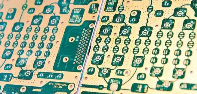
Introduction to PCB Materials
Printed Circuit Board (PCB) materials are categorized by quality, performance, and application. Choosing the right material is critical for durability, thermal management, and electrical performance. This guide explains PCB material grades, key parameters, and selection criteria for optimal design.
PCB Material Classification (Low to High Grade)
| Material | Description | Key Properties | Common Applications |
|---|---|---|---|
| 94HB | Non-flame-retardant cardboard | Low cost, die-punched, weak thermal resistance | Low-cost electronics, toys |
| 94V0 | Flame-retardant cardboard | Self-extinguishing, UL94V-0 compliant | Basic consumer electronics |
| 22F | Single-sided semi-glass fiberboard | Moderate strength, die-punched | Simple single-layer boards |
| CEM-1 | Single-sided fiberglass board | Requires drilling, better durability | LED lighting, power supplies |
| CEM-3 | Double-sided semi-glass fiberboard | Cost-effective, good for simple designs | Double-sided boards, low-cost PCBs |
| FR-4 | Double-sided fiberglass board | High thermal/mechanical stability | Multilayer PCBs, high-frequency circuits |
Key PCB Material Properties
1. Flame Retardant Ratings (UL94 Standard)
-
94HB – Low flame resistance
-
V-1/V-2 – Moderate self-extinguishing
-
94V0 – Highest flame resistance (critical for safety compliance)
2. Prepreg Thickness Options
Prepreg layers bond PCB cores in multilayer boards:
-
1080 (0.0712 mm) – Thin, high-density designs
-
2116 (0.1143 mm) – Balanced thickness
-
7628 (0.1778 mm) – Thick, high mechanical strength
3. Halogen-Free PCBs (Eco-Friendly Option)
-
No bromine/chlorine – Reduces toxic fumes when burned
-
RoHS & REACH compliant – Required for EU markets
4. Glass Transition Temperature (Tg)
-
Standard Tg (≥130°C) – Basic consumer electronics
-
Mid Tg (≥150°C) – Industrial applications
-
High Tg (≥170°C) – High-power, automotive, aerospace
Why High-Tg Matters:
✔ Better heat resistance
✔ Improved mechanical strength
✔ Essential for lead-free soldering
PCB Manufacturing Specifications
| Parameter | Standard Range |
|---|---|
| Max Board Size | Up to 600 × 700 mm |
| Thickness | 0.4–4.0 mm |
| Copper Weight | 0.5–4.0 oz |
| Min Trace Width | 0.1 mm (4 mil) |
| Min Drill Hole Size | 0.25 mm (10 mil) |
| Dielectric Constant (ε) | 2.1–10.0 |
| Thermal Shock Resistance | 288°C for 10 sec |
How to Choose the Right PCB Material
1. Consider Thermal Requirements
-
High-power circuits? → FR-4 or High-Tg
-
Basic electronics? → CEM-3 or 94V0
2. Check Compliance Needs
-
Flame resistance? → 94V0 or FR-4
-
Eco-friendly? → Halogen-free FR-4
3. Assess Mechanical Demands
-
Flexible PCBs? → Polyimide (PI)
-
High-frequency signals? → Low-Dk materials
Conclusion: Best PCB Material for Your Project
-
Budget-friendly? → CEM-1 or CEM-3
-
High-performance? → FR-4 or High-Tg
-
Eco-conscious? → Halogen-free options
By understanding PCB material properties, you can optimize performance, cost, and reliability. Need help selecting the right material? Consult with a PCB manufacturer for tailored recommendations.

Recent Comments