

Effective PCBA Testing is the structured quality process that confirms a populated circuit board has been assembled correctly, performs as intended, and is ready for integration into a finished product. At Fuxin PCBA, testing is not a final checkpoint — it is built into every stage of turnkey PCBA manufacturing, from incoming component inspection to functional verification before shipment. A strong testing plan combines visual inspection, electrical verification, functional testing, and process feedback so defects are caught early rather than after delivery. This guide explains the core methodologies used in circuit board testing and how they fit into reliable electronics production.
What Does Effective PCBA Testing Actually Involve?
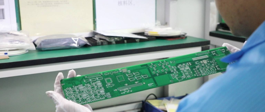
Effective PCBA Testing involves more than powering on a board and seeing whether it works. It is a layered quality process that checks physical assembly, electrical behavior, component placement, solder integrity, and real-world function. The goal is to catch manufacturing defects, design-related issues, and performance problems before the board reaches the next production stage.
A complete approach usually starts with assembly inspection, then moves into electrical and electronic testing, and finally validates performance through pcba functional testing. Each stage answers a different question. Was the board built correctly? Are there shorts, opens, or missing components? Does the board behave correctly under expected operating conditions?
This layered strategy matters because no single test method finds every problem. Visual inspection may identify solder bridging or reversed polarity, but it will not validate embedded firmware behavior. Functional testing can confirm system operation, but it may not reveal every marginal solder joint. Used together, these techniques create a practical safety net.
The Role of Inspection Before Electrical Testing
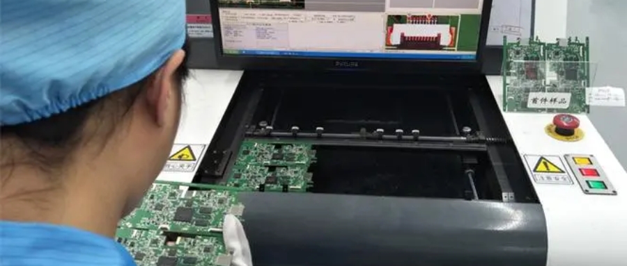
Inspection is the first opportunity to prevent obvious assembly defects from moving forward. It focuses on the physical condition of the PCBA: component placement, solder joints, polarity markings, alignment, cleanliness, and signs of handling damage. In many production settings, inspection begins immediately after soldering and continues through later quality checkpoints.
Manual inspection remains useful for prototypes, low-volume builds, rework validation, and unusual components. However, human inspection has limits. Small packages, dense layouts, and fine-pitch components make it difficult to see every issue consistently. That is why most manufacturers combine manual review with automated inspection methods.
A practical assembly inspection process may include:
Component presence and orientation — confirms required components are installed and positioned correctly.
Solder joint quality — looks for bridges, insufficient solder, excess solder, voids, tombstoning, or cold joints.
Connector and mechanical alignment — verifies headers, ports, switches, and sockets sit correctly for enclosure fit.
Board cleanliness — checks for residue, debris, loose solder balls, or contamination.
Labeling and traceability — confirms revision markings, serial numbers, barcodes, or batch identifiers.
Inspection does not replace circuit board testing, but it improves test efficiency. A board with a visible short or missing part should not consume time in a functional test fixture before the physical problem is corrected.
Core Testing Methodologies Used in PCBA Production
Different testing methodologies serve different purposes. The right mix depends on board complexity, production volume, risk level, and available test access. A simple LED controller may need a lean process, while a communication module, power supply, or medical device subassembly may require more extensive validation.
Visual and Automated Optical Inspection (AOI)
Visual inspection and automated optical inspection focus on what can be seen from the board surface. AOI uses cameras and programmed criteria to detect placement and solder defects. It is especially useful in surface-mount assembly because it can review many solder joints quickly and consistently.
AOI is strongest when configured around known design data and manufacturing tolerances. It can identify missing parts, skewed components, incorrect polarity, and visible solder defects. Its limitation is that it cannot fully test internal electrical behavior, hidden joints under certain packages, or component values unless supported by additional methods.
X-Ray Inspection for Hidden Solder Joints
Some components hide their solder connections underneath the package. Ball grid arrays, bottom-terminated components, and certain leadless packages can make surface inspection incomplete. X-ray inspection evaluates these hidden joints by showing internal solder structure and alignment.
This method is valuable when failures are difficult to detect visually or when board designs use packages with inaccessible solder joints. It can help identify bridging, voiding, insufficient solder, and alignment issues. Because it is more specialized, it is often used selectively for higher-risk assemblies, first articles, prototypes, or boards with known challenging components.
In-Circuit Testing (ICT)
In-circuit testing checks individual nodes and components on the assembled board, often through test pads or a bed-of-nails fixture. It can identify shorts, opens, incorrect values, missing components, and other assembly-related issues before the board is evaluated as a complete system.
This technique works best when the board design includes adequate test access. During design for manufacturability planning, engineers should consider where probes will contact the board, how stable those contact points are, and whether important nets can be isolated for measurement. Without sufficient access, in-circuit testing may be limited or require alternative strategies.
Flying Probe Testing
Flying probe testing uses moving probes rather than a dedicated bed-of-nails fixture. It is often useful for prototypes, engineering builds, and lower-volume production because it avoids the cost and lead time of a custom fixture. The probes can measure continuity, resistance, capacitance, shorts, opens, and other electrical characteristics.
The tradeoff is speed. Flying probe testing is generally slower than fixture-based testing, so it may not be ideal for high-volume production where cycle time is critical. However, for early builds and design validation, it offers flexibility and can uncover issues before the process is scaled.
Why Functional Testing Is So Important
Functional testing is important because it verifies whether the assembled board performs the job it was designed to do. While inspection and electrical checks confirm that parts are present and circuits are connected, functional testing evaluates real behavior: power-up sequence, signal response, communication, sensor input, output control, firmware interaction, and other application-specific functions.
In pcba functional testing, the board is typically placed in a fixture or connected to test equipment that simulates its operating environment. Inputs are applied, outputs are measured, and pass/fail criteria are compared against expected behavior. For example, a motor control board may be tested for voltage regulation, control response, fault detection, and communication with a host system.
Functional testing is especially valuable because it catches issues earlier tests may miss. A component may be soldered correctly but programmed incorrectly. A power rail may be present but unstable under load. A communication interface may pass basic continuity checks but fail when actual data is transmitted.
Elements of a Strong Functional Test
A useful functional test should define:
Test objectives — the specific functions, outputs, and operating modes being verified.
Required equipment — fixtures, power supplies, loads, measurement devices, and software tools.
Input conditions — signals, commands, voltages, environmental assumptions, or simulated system interactions.
Pass/fail limits — acceptable measurement ranges and performance thresholds.
Data capture — test results, serial numbers, failure codes, and operator notes where traceability is needed.
Failure handling — clear instructions for quarantine, diagnosis, rework, retest, or engineering review.
The best functional tests are repeatable and specific. “Board works” is not a test standard. A stronger standard defines exactly what must happen, under what conditions, and within what tolerance.
Power-On and Safety Checks Protect the Board
Before a PCBA is subjected to full functional testing, it is common to perform basic power checks. These reduce the risk of damaging the board, test fixture, or connected equipment. They also help isolate fundamental failures before more complex diagnostics begin.
A careful power-on process may start with current-limited power, verification of primary rails, and checks for abnormal heat or excessive current draw. If a board pulls too much current immediately, continuing into full testing may create additional damage. Early shutdown criteria protect both the product and the test station.
For boards with multiple voltage domains, sequencing can be important. Some assemblies require specific startup timing or enable signals before the full circuit becomes active. A good electronic testing plan accounts for these details so a valid board is not mistakenly failed because it was powered incorrectly.
Boundary Scan and Firmware-Related Checks
Boundary scan testing can be useful when physical probe access is limited, especially on dense digital boards. It uses built-in test capabilities in compatible integrated circuits to check interconnections and detect certain faults without direct access to every node. This is helpful when modern packaging or layout constraints reduce test pad availability.
Firmware and programming checks are also essential for many PCBAs. A board may need a bootloader, application firmware, configuration data, calibration values, or security settings before it can function properly. Testing should confirm not only that programming completed, but also that the correct version or configuration is present.
These checks bridge the gap between manufacturing and product behavior. In turnkey PCBA manufacturing, where sourcing, assembly, programming, and testing may be handled within one coordinated process, firmware control and revision tracking become especially important. A mismatch between hardware revision and firmware version can create failures that look like assembly defects but are actually configuration problems.
Choosing the Right Test Mix for the Product
The right PCBA Testing strategy depends on risk, cost, volume, and product complexity. More testing is not automatically better if it adds time without improving defect detection. The goal is to choose a test mix that finds likely failures efficiently and supports the quality level required by the application.
A prototype build may benefit from flexible methods such as manual inspection, AOI, flying probe testing, and detailed engineering functional tests. A mature production run may use automated inspection, fixture-based electrical testing, programmed functional testing, and statistical review of failures. High-reliability products may also require deeper traceability and more rigorous acceptance criteria.
Practical test selection checklist:
What are the most likely assembly defects for this design? Fine-pitch parts, polarity-sensitive components, and dense layouts often need closer inspection.
Which failures would be most costly if found late? Prioritize tests that catch defects before final integration or shipment.
Is test access designed into the board? Add test pads, connectors, or boundary scan support where appropriate.
What functions must be proven on every unit? Identify critical outputs, communication links, power rails, and safety-related behavior.
How much production volume is expected? Custom fixtures may make sense for repeat builds but may be excessive for small prototype runs.
What data should be recorded? Decide whether pass/fail logs, measurements, serial tracking, or failure codes are needed.
This checklist helps align testing with product reality instead of applying a generic process to every board.
How Testing Fits into Turnkey PCBA Manufacturing
In turnkey PCBA manufacturing, testing works best when it is planned before assembly begins, not added at the end. Because the manufacturing partner may handle procurement, fabrication coordination, assembly, programming, inspection, and testing, the test strategy should be connected to the full production workflow.
Early planning helps avoid common problems such as missing test points, unclear pass/fail criteria, unavailable programming files, or fixtures that do not match the final board revision. It also allows the test process to reflect component availability, assembly sequence, and production volume. When testing is treated as part of manufacturing rather than a separate afterthought, defects are easier to isolate and corrective actions are easier to apply.
Good communication is central. The manufacturer needs current design files, bill of materials details, firmware requirements, expected operating behavior, and any known risks. The customer or engineering team should define what successful performance means. Together, these details turn testing from a vague quality step into a repeatable production control.
Turning Test Results into Process Improvements
Testing is not only about sorting good boards from bad boards. It also produces feedback that can improve assembly quality, design robustness, and future production efficiency. When failures are tracked by type, location, batch, and root cause, patterns become easier to see.
For example, repeated solder defects around a specific component may suggest stencil, placement, or reflow profile adjustments. Recurring functional failures on one interface may point to a design margin issue, firmware configuration problem, or fixture limitation. Without structured failure data, teams may repair individual boards while missing the larger cause.
A strong feedback loop includes failure logging, root-cause analysis, corrective action, and retesting. The aim is not simply to increase the number of tests. The aim is to reduce preventable failures and make each stage of production more predictable.
Best Practices for Reliable Circuit Board Testing
Reliable circuit board testing starts with design choices and continues through documentation, fixture development, operator training, and result review. Even advanced equipment can produce poor outcomes if the process is unclear or inconsistent.
Important best practices include designing for test access, defining measurable pass/fail limits, validating fixtures before production use, and keeping test procedures aligned with the latest board revision. It is also wise to separate diagnostic tests from production acceptance tests. Engineering teams may need deep diagnostic capability, while production teams need efficient, repeatable checks that support consistent throughput.
Documentation should be specific enough that different operators can run the same test and reach the same conclusion. If a failure requires judgment, the procedure should explain what to inspect next or when to escalate. Consistency reduces false failures, missed defects, and unnecessary rework.
A Layered Approach Builds Better Confidence
No single testing method can guarantee a flawless PCBA, but a layered process can greatly improve confidence before boards move forward. Assembly inspection catches visible defects, electrical testing verifies circuit integrity, and functional testing confirms real operating behavior. Together, these techniques support a more reliable manufacturing process and a stronger finished product.
For teams developing or sourcing electronics, the most important step is to plan testing early. Define what must be inspected, what must be measured, what must be functionally proven, and what data should be recorded. When PCBA Testing is built into the production strategy from the start, it becomes more than a checkpoint — it becomes a practical tool for quality, consistency, and long-term improvement.
Frequently Asked Questions
What is PCBA testing?
PCBA testing is the structured quality process that verifies a populated circuit board has been assembled correctly and performs as intended. It includes inspection, electrical testing, and functional testing.
What is the difference between PCBA testing and PCB testing?
PCB testing checks the bare board before components are mounted. PCBA testing verifies the fully assembled board, including solder joints, component placement, electrical behavior, and functional performance.
What is PCBA functional testing?
PCBA functional testing verifies that the assembled board performs its intended function — power-up sequence, signal response, communication, sensor input, and output control — under simulated operating conditions.
When should AOI or X-ray inspection be used?
AOI is used for visible solder joints and component placement on surface-mount assemblies. X-ray inspection is used for hidden solder joints under BGA, QFN, and other bottom-terminated packages.
What is the difference between in-circuit testing and flying probe testing?
In-circuit testing uses a dedicated bed-of-nails fixture for high-volume production. Flying probe testing uses moving probes and is better suited for prototypes and low-volume builds.
Why is testing important in turnkey PCBA manufacturing?
In turnkey PCBA manufacturing, testing is planned before assembly begins. It connects procurement, assembly, programming, and inspection into one coordinated workflow, so defects are caught early and corrective actions are applied faster.
Need a Reliable PCBA Testing Partner?
Fuxin PCBA provides one-stop PCB assembly and OEM services, covering PCB fabrication, component sourcing, SMT and DIP assembly, AOI, X-ray inspection, in-circuit testing, flying probe testing, and functional testing. We support industrial, medical, telecommunications, automotive, multimedia, consumer electronics, clean technology, and oil & gas clients.
Send us your Gerber files and BOM for a response within 3 business days.